In my role as a technical trainer frequently engaged in workplace training, I’m always interested to observe various technicians’ perceptions towards the electrification of vehicles. Whilst we have many enthusiastic technicians that have always embraced change and have kept themselves up-to-date with the latest advancements in all things automotive, I sense a degree of apprehension in others citing various reasons for their lack of enthusiasm towards Hybrid or EV’s.
What has become quite apparent is that some repairers can feel overwhelmed by many articles published speaking of such things as fully autonomous vehicles and the other futuristic whiz-bang technology implying that cars will magically self-heal, fly, never need fixing, wash themselves, whatever!
Regardless of which technologies actually make it to the mainstream marketplace, we need to take a step back, take a deep breath and de-mystify how EV’s actually work. It’s essential to understand how to test and repair them safely. We need to identify future opportunities for the aftermarket and repair sectors by gaining a clearer picture of the components and operation of a Hybrid/EV. For that reason, over the upcoming editions I want to present an in-depth look at the various systems that come together to make an EV work.
Firstly, I need to point out the obvious danger of working with high voltage systems. While some mild hybrid systems operate on voltages lower than 60V, strong hybrids and full EV’s will operate on voltages above 200V with a large amount of energy in storage. This provides a potentially dangerous situation for those not applying correct procedures, PPE and tooling/equipment. I strongly recommend that anyone planning to engage in Hybrid/EV servicing or repairs (which will be most of us) attend an accredited training course where processes such as depowering, reinitialising, servicing and maintaining Hybrid and EV’s are covered in detail.
In low voltage systems, we use a battery (usually 12V or 24V) where the vehicle’s chassis is directly connected to battery negative (chassis ground) and battery positive is insulated from ground and distributed to the various systems and components via a maze of fuse / busbars, splices, relays etc. If there is an earth leakage of some description, there is a possibility of a blown fuse, leakage current or improper electrical performance of some kind. However, none of these events are considered life threatening since we are dealing with a low voltage system.
A high voltage system presents us with an inherent danger and is defined as a system running 60 or more volts. As with most vehicle design these days, a myriad of ISO and other standards means that all engineers / vehicle designers need to comply with a range of mandatory requirements when developing a typical EV powertrain. In the case of a high voltage HEV / EV the HV battery positive and negative are completely isolated from the chassis of the vehicle however there is a 12V system using chassis ground to provide power for many of the regular components we’re accustomed to such as many dashboard functions (HVAC will be HV), windows, interior lighting, door locking etc.
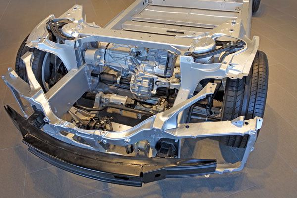
EV’s and HEV’s are designed in a myriad of different layouts and configurations which at first can seem confusing. For example, Toyota Prius and Camry have two motor / generators housed in a transaxle; Mitsubishi Outlander has two electric MG’s, one located at the front and one at the rear; Tesla Model 3, RWD drive motor assembly; GM (Hybrid) BAS system, belt, alternator starter, parallel hybrid systems with an electric motor taking up the traditional space inside the bellhousing, and the list goes on.
Despite the range of Hybrid/EV vehicles on the market, they all have many features in common so by understanding the operating principles and purpose of the various components that make up an EV system, we can then apply that knowledge to any make or design we encounter. The electronic design involved in any contemporary vehicle draws on many disciplines within the industry such as data transfer, processing, programming etc. EV’s are no different, however they draw heavily on power electronics technology. Power electronics is defined as ‘the application of solid-state electronics to the control and conversion of electric power’, which is in contrast to electronic systems concerned with transmission and processing of data.
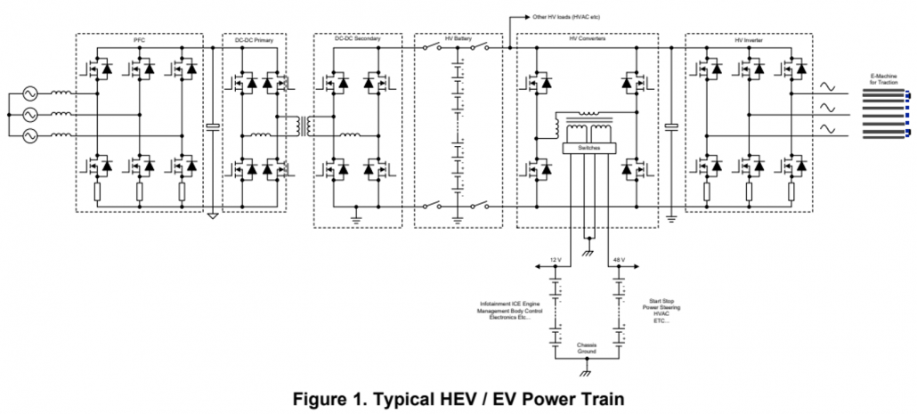
Starting at the left of the diagram is the PFC (Power Factor Correction Unit) which is simply a power control unit to rectify (AC to DC) and raise or lower the voltage required to charge the batteries. This unit will not be present on an HEV but is necessary on all PHEV and EVs since they require an external charge connection. The unit will most likely have the ability to take power from a single or 3-phase supply. In the centre of the diagram is the HV battery consisting (usually) of Lithium batteries. We will cover battery types in detail in a later article. To the right of the HV battery pack is a 3-phase bridge (powers and controls the motor) and a 3-phase motor on the far right. The lower section of the diagram shows a 12V and 48V circuit.
When we break these systems down to fully understand their operation, we always encounter the same principles over and over. For example: DC – DC conversion to shift voltage levels up and down as required (Buck – Boost converters), isolation transformers to increase or decrease an AC voltage, rectification to convert AC to DC, H bridges, 3-phase bridges (motor drive), motor commutation and voltage, Sine PWM techniques, isolation leakage detection, capacitors, safety interlock systems, battery technology and battery management systems, inverter/convertor assemblies, battery and electronics cooling etc.
Over the upcoming articles, we will have a more detailed look at individual components and circuit design. Until then stay tuned!
Source: Motor Trader E-magazine (June 2020)
21 May 2020