Alternating and Direct current requirements of Hybrid / Electric vehicles. Conversion of DC to AC.
Alternating current is used in almost all residential, commercial and industrial needs. The biggest issue with AC is that it cannot be stored for future use. So, AC is converted to DC (rectified) and then stored in batteries, ultracapacitors etc. The charging source of AC for an Electric Vehicle (EV) can be a charging station, wall socket, or recovery from the vehicles three-phase drive motors when braking. Rectification of AC to DC is relatively easy, achieved with something as simple as a diode bridge rectifier that we have become familiar in alternators for many years. In EV’s and high-power applications the diodes will most likely be replaced with MOSFETs (metal oxide semiconductor field-effect transistor) due to their low forward conductance voltage and power handling capability. However, the basic principle remains the same.
This article will take a sightly in-depth look at Voltage Inversion (converting a DC power supply to AC).
Many components of an EV require a sinusoidal AC source for efficient operation, such as three-phase PMSM motors (permanent magnet synchronous motor) and transformers.
The challenge here is to take a DC source (batteries) and convert the DC back to AC in the form of a pure sine wave. It is relatively easy to produce a sine wave to provide electrical currents in the order of milliamps for signal generation, but when a large amount of power is required a different approach is taken.
The method commonly used in power electronics is a technique referred to as SINE PWM. Most of us will be familiar with PWM (pulse width modulation) as it is an efficient method used to control such things as DC motor speed, light intensity and diesel glow plug control.
Just as a quick refresher here for those that are a little rusty on PWM it works as follows:
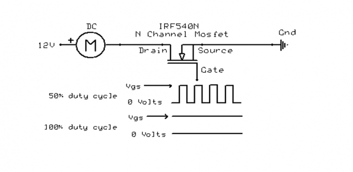
(Figure 1)
In the example of Figure 1, a constant power supply of 12 volts is applied to one terminal of a brushed DC motor. The negative side is connected to the drain of an N-Channel MOSFET. The MOSFET source connects to negative/ground and the Gate is pulsed to turn the MOSFET on. The MOSFET is turned on and off very quickly. Carrier frequencies greater than 5Khz are commonly used.
If the MOSFET is on 50 per cent of the time and off 50 per cent of the time then current flow and apparent voltage across the motor is 50 per cent. If the MOSFET is on 100 per cent of the time, the motor runs at full speed. So basically, it gives analogue control using a digital technique which is far more efficient than using a variable series resistance which would waste energy due to power dissipation/heating across the resistance.
If insufficient voltage is applied to the gate of the MOSFET it will be partially turned on (operating in its Active Region) and therefore acting as a resistor in the circuit which will reduce the speed of the motor. However, the device will be dissipating power, heating up, wasting energy and possibly fail.
Power MOSFETS are intended to be operated in either the saturated/linear region, or the cut-off region. In other words, they work best tuned fully on, and fully off. Time in the transitional state in between off/on must to be avoided.
The table above demonstrates the difference in power dissipation at 10amps operating the MOSFET in its minimum Rds on / linear region dissipating Vs partially turned on in its active region with 1.0 Ω resistance and dissipating 100W of power.
Ok, now that we have PWM out of the way, what is Sinusoidal PWM (SPWM)? And why do we need it?
Well here’s an example:
In some cases, a transformer will be used to step down a voltage from say 200V to somewhere around 14V which would be used to charge a lead-acid battery and provide power for devices such as power windows, interior lights, and accessories at a safe, low voltage. Something similar to what we would find in a Toyota Prius for example.
A single-phase transformer consists of a primary winding where the power is fed in and shares a common magnetic core with a secondary winding which supplies the power. There is no direct connection between the primary and secondary windings but they are magnetically coupled, which provides a level of safety by isolating the high voltage AC primary from the secondary. A transformer does not work with DC and requires AC to provide electromagnetic induction to induce voltage into the secondary winding.
Armed with this information, you may think ‘OK, let’s just switch the polarity of the primary continuously by reversing a DC voltage across the primary and we’ll get an output from the secondary’. This is a similar approach to building and collapsing a magnetic field in an ignition coil and inducing a much higher voltage into the secondary because of the winding ratio. Easy right?
The problem is that you would be applying a square wave to a coil which produces higher order harmonics resulting in less efficiency, unwanted heat and more stress on the winding. This is not what we want for efficient and smooth operation of three-phase motors, transformers etc. A sine wave gives a smooth periodic oscillation.
Here’s how it’s done:
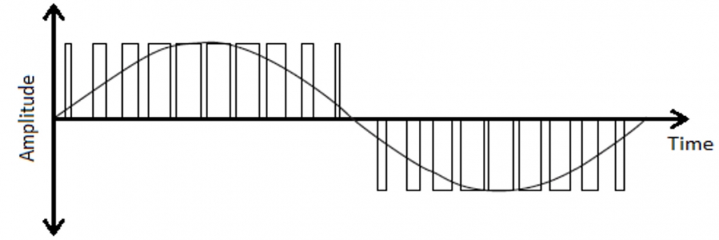
(Figure 2)
In Figure 2, it can be seen that a switching event begins with a very narrow pulse gradually increasing until a duty cycle of 100 per cent is achieved and then the pulse width is gradually reduced back to zero. The average line through the PWM represents what is seen on an oscilloscope when the output is low pass filtered. In the case of a transformer primary or a three-phase motor, the winding itself would be the low pass filter (LPF). In the case of a three-phase motor, three sine waves are needed 120° apart.
A low pass filter is a circuit which blocks high frequencies and allows lower frequencies to pass. There are a number of methods which can be used for Low Pass Filtering but a simple passive LPF may simply consist of a resistor and capacitor. In the case of a motor or transformer, the winding is the low pass filter due to the inductive nature of a coil.
Two PWM signals are required, and typically generated in a microcontroller by programming an array. An array is basically a look-up table with consecutive memory locations. By using the microcontrollers on-board timer-counter and an interrupt service routine, two sine PWM outputs 180° apart are generated (for a single phase). The subject of coding and microcontrollers are beyond the scope of this article but to give you an idea, this can be achieved easily with a small 8-bit microcontroller with around 8KB of memory, giving a maximum SPWM resolution of 255 steps.
In this configuration the microcontroller provides a 0V – 5V SPWM output on two pins, used to trigger either a MOSFET half bridge or full bridge as required.
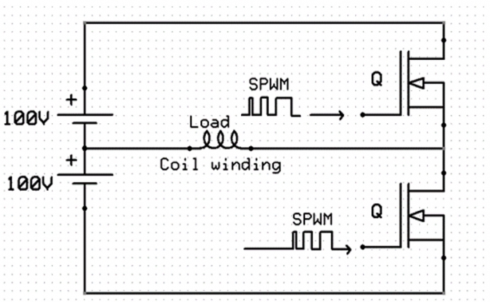
(Figure 3)
Figure 3 shows a Half Bridge. For the Half Bridge to operate, two sine PWM signals 180° apart are generated. Care must be taken by the designer to ensure that only one MOSFET is turned on at once. A condition known as shoot-through can occur if one MOSFET begins conducting before the other MOSFET has turned off. The power supply has to be split to provide a virtual neutral point which allows positive and negative transitions of the sine wave. A Half Bridge provides a reduction in components but can only produce voltages up to half supply voltage. As can be seen, the winding / load is positioned so that current will flow in opposite directions depending on which MOSFET is turned on.
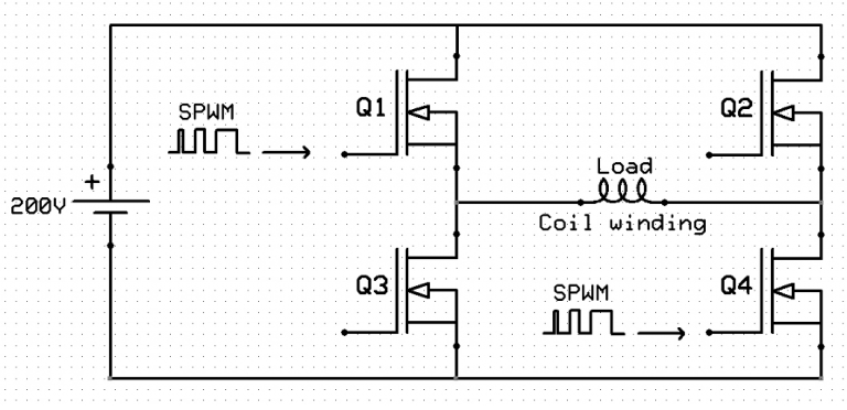
(Figure 4)
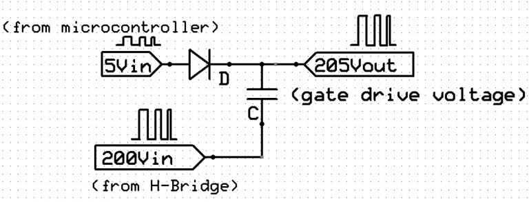
Figure 4 shows an H Bridge – often referred to as a Full Bridge – which requires 4 MOSFETS. A Full Bridge does not require a split power supply to provide the positive and negative going transitions of the sinewave. A Full Bridge can produce outputs equal to supply voltage. As with the Half Bridge, care must be taken in the design to ensure proper switching of the MOSFETS to prevent shoot-through. The Gate voltage required in both Half and Full Bridges to turn the high side MOFETS on (Q1 & Q2) is critical and generally must be at least 5 volts higher than the source voltage. Failure to provide sufficient gate voltage will result in the MOSFET dissipating excessive power and overheating. For example, if Q1 turns on, then Q4 will be on at the same time. Because the high side of the load (Q1 source voltage) will be at a potential of 200V, an additional 5V is required to turn Q1 on fully. A bootstrap circuit will provide the additional voltage shift from 200V to 205V.
(Figure 5)
Figure 5 shows a circuit commonly referred as a Dickson Voltage Doubler. This is a type of bootstrap circuit which can increase the output above supply voltage. Bootstrapping works on this principle.
As technologies improve there are various types of power switching devices available, ranging from the Bipolar Junction Transistor (invented in 1947), to MOSFETS, IGBT’s (Integrated Gate Bipolar Transistors), SIC MOSFETs (silicon carbide) etc. For the sake of this article I have referred to the switching device as a MOSFET.
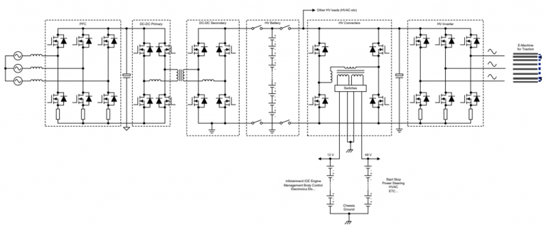
In my previous article, I presented the schematic diagram of a typical EV power train (Figure 6).
(Figure 6)
The diagram shows the basic layout typical of an electric vehicle. It’s obvious that the circuitry relies heavily on H Bridge and three-phase bridges which are the heart of any modern Hybrid/Electric vehicle. The DC to DC primary uses SPWM to drive the transformer primary winding The DC to DC secondary uses MOSFETs as a rectifier to convert AC to DC to charge the batteries (high voltage).
Another H Bridge is used to generate AC voltage to a step-down transformer to provide the 12V system power requirements.
As I mentioned in the previous article, the system consists of a Power Factor Correction unit which rectifies an external AC charging source to DC and alters the voltage level required to charge the batteries. The unit should at least be capable of taking a single-phase input for general domestic charging from a wall socket or three-phase supply for faster charge. Note the use of an H Bridge.
(Figure 7)
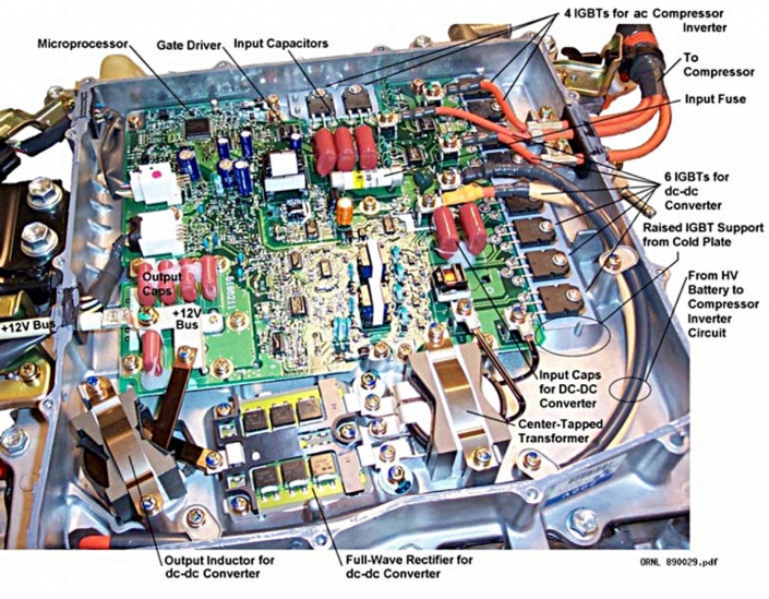
Figure 7 shows the actual layout of a Toyota Hybrid inverter-converter unit. Note the 6 IGBTs for the A/C compressor drive motor and the tapped transformer. These components amongst other will require an SPWM control.
It’s also worth noting the gate driver IC which will provide the necessary bootstrap voltage applied to gate of the IGBT high side drivers.
(Figure 8)
(Figure 9)
(Figure 10)
(Figure 11)
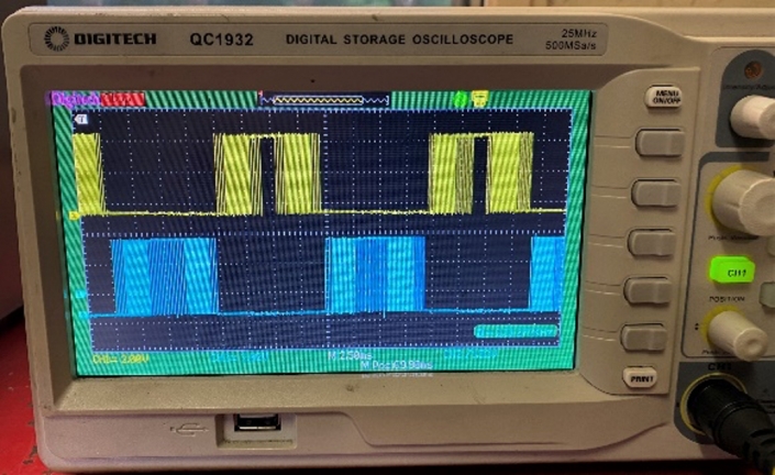
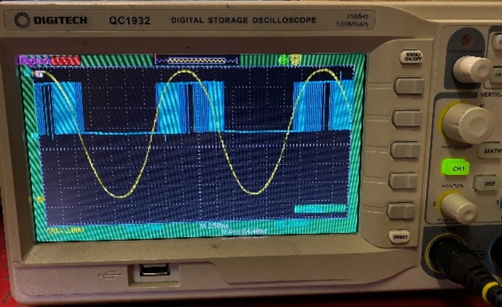
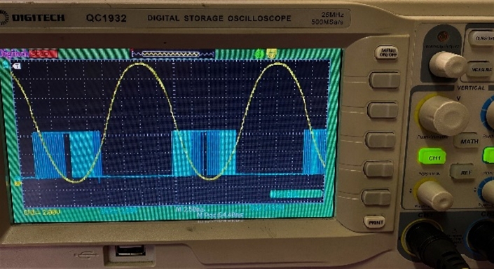
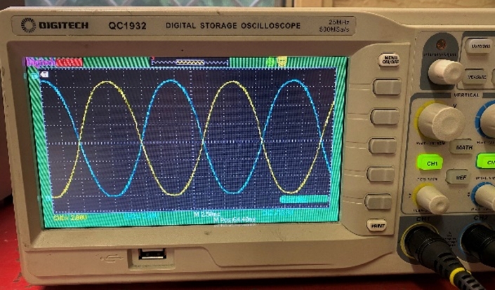
Figures 8 to 11 demonstrate the actual operation of a single-phase AC inverter generating a 50Hz sine wave. The images demonstrate the 5V SPWM signal generated on two microcontroller pins used to switch the MOSFETS in an H Bridge. An 8-bit microcontroller was used with an internal clock speed of 8MHz, and the timer/counter was clocked at approximately 3MHz to produce a 50Hz AC sine wave.
(Figure 12)
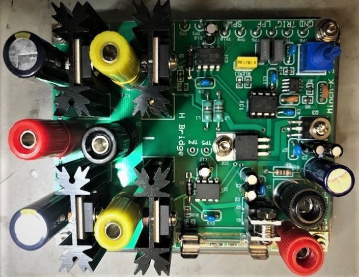
The image above demonstrates a circuit developed to demonstrate the implementation of sine PWM. The unit enables easy access for oscilloscope and electronics training purposes.
In conclusion, it can be seen that all Hybrid / EV’s rely heavily on AC to DC conversion (rectification) and DC to AC conversion (inversion). In addition, voltage levels need to be increased and decreased to satisfy particular demands of the vehicles design. Whether the vehicle runs on a 48V system or a 600V system, the operating principles remain the same.
In future articles I will cover DC to DC conversion, motor drive techniques, high voltage isolation and leakage detection, isolated CAN bus and latest 48V system developments.
I have gone into to some detail with this article, which may be beyond the needs of many people engaged in the automotive sector. Some of you may find things a bit overwhelming as we transition towards the electrification of vehicles. The MTA Institute provides in-house training courses suited to the everyday needs of those engaged in all aspects of Hybrid – Electric vehicle repairs so that we can make this transition safely and confidently.
Until next time stay tuned and work safely.
Source: Motor Trader E-magazine (July 2020)
10 Jul 2020

